Power electronics is the application of solid-state electronics to the control and conversion of electric power.
✏️TYPES OF POWER ELECTRONICS CIRCUITS
1. Diode rectifiers
2. Ac–dc converters (controlled rectifiers)
3. Ac–ac converters (ac voltage controllers)
4. Dc–dc converters (dc choppers)
5. Dc–ac converters (inverters)
6. Static switches
1. Diode rectifiers
➡️A diode rectifier circuit converts ac voltage into a fixed dc voltage.
2. Ac–dc converters (controlled rectifiers)
➡️A single-phase converter with two natural commutatedthyristors is shown in Figure. The average value of the output voltage v 0can be controlled by varying the conduction time of thyristors or firingdelay angle , The input could be a single- or three-phase source. Theseconverters are also known as controlled rectifiers.
3. Ac–ac converters (ac voltage controllers)
➡️These converters are used to obtain a variable ac outputvoltage from a fixed ac source and a single-phase converter with a TRIAC isshown in Figure. The output voltage is controlled by varying the conductiontime of a TRIAC or firing delay angle , These types of converters are alsoknown as ac voltage controllers.
4. Dc-dc converters
➡️A dc–dc converter is also known as a chopper, orswitchingregulator, and a transistor chopper is shown in Figure. The averageoutput voltage v 0 is controlled by varying the conduction time t, oftransistor Q1. .If T is the chopping period, then t1 = T. is called as theduty cycle of the chopper.
5. DC-AC converters
➡️A dc–ac converter is also known as an inverter. Asingle phase transistor inverter is shown in Figure. If transistors M1 andM2 and conduct for one half of a period and M3 and M4 conduct for theother half, the output voltage is of the alternating form. The outputvoltage can be controlled by varying the conduction time of transistors
6. static switches
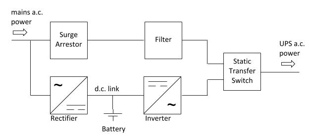
➡️Because the power devices can be operated as static switches orcontactors, the supply to these switches could be either ac or dc and the switches arecalled as ac static switches or dc switches.A number of conversion stages are often cascaded to produce the desired outputas shown in Figure . Mains 1 supplies the normal ac supply to the load through thestatic bypass. The ac–dc converter charges the standby battery from mains.
2.The dc–ac converter supplies the emergency power to the load through an isolang transformer.Mains 1 and mains 2 are normally connected to the same ac supply.
✏️APPLICATION OF POWER ELECTRONICS
🔋Power electronics have revolutionized the concept of power control for powerconversionand for control of electrical motor drives.Power electronics combine power, electronics, and control.
🔋Control deals with the steady-state and dynamic characteristics of closed-loop systems.
🔋Power deals with the static and rotating power equipment for the generation,transmission, and distribution of electric energy.
🔋Electronics deal with the solid-state devices and circuits for signal processing tomeet the desired control objectives.Power electronics may be defined as the applications of solid-state electronics for thecontrol and conversion of electric power.Power electronics are based primarily on the switching of the power semiconductor devices.


No comments:
Post a Comment
If you have any doubts or clarification you need in my blog topics, I would 💯 try to clear it in an efficient manner as possible. I will also accept your suggestions.